From FDM
What is a liquid mirror ?
It has been known for several centuries that the surface of a spinning liquid takes the shape of a paraboloid that could, in theory, be used as a telescope's primary mirror. One can easily verify that by adding the vectors of centripetal and gravitational accelerations, one obtains a parabolic surface. The first known mention of a liquid parabolic mirror was made by the Italian astronomer Ernesto Capocci around 1850.
The focal length f of a liquid mirror is related to Earth's gravitational field g and the angular velocity ω of the turntable by:

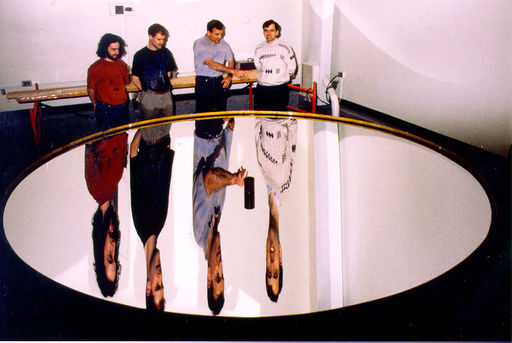
For large mirrors of practical interest in astronomy, optimal rotational periods are of the order of 10 seconds, with linear velocities at the edge between 5 and 20 kilometers per hour. The photograph below shows a mercury liquid mirror with a diameter of 3.7 meters that has been extensively tested in our laboratory at Laval University.
If you would like to know more about liquid mirrors, why not download : Liquid Mirrors: A Review by Ermanno Borra published in the Canadian Journal of Physics in 1995.
If you're interested in the history of liquid mirrors, download Brad Gibson's paper: Liquid Mirror telescopes : History and learn how the concept evolved to give the liquid mirror we know. Otherwise you might find what you're looking for in our publications.
Why liquid mirrors ?
In the past, the concept of liquid mirrors (LMs) was never seriously considered for research for two main reasons. First, early attempts to make such mirrors were only partially successful, giving a bad reputation to the concept. Second, liquid mirrors were only considered for astronomical applications, for which they have an obvious limitation: they cannot be tilted and therefore cannot be pointed towards or track specific objects in the way that conventional telescopes can. This is a major drawback that made LMs highly impractical in astronomy.
Modern technology however now gives us alternate tracking techniques that render liquid mirrors useful to astronomy: for imagery, narrow-band filter spectroscopy or slitless spectroscopy, one can use a technique called time delayed integration that uses a CCD detector that tracks by electronically stepping its pixels. The information is stored on disk and the nightly observations can be added with a computer to give long integration times. The technique has been used for some time with fixed telescopes, and imagery with a liquid mirror telescope has been demonstrated by Hickson et al. at UBC.
We were drawn to consider liquid mirrors because they present two main advantages over conventional glass mirrors: they are considerably cheaper (up to a factor of 100!) and it should be possible to build them to much larger diameters. Having concluded that it would be worthwhile, in light of modern technology, to explore the liquid mirror concept Ermanno Borra began a feasibility study to determine the conceivability of an optical-quality surface on a spinning liquid. Early tests gave very positive results, and, using more advanced testing facilities it was determined that a 1.5 m diameter liquid mirror had such good optical quality that it was diffraction-limited. This was followed by the construction and testing of 2.5 m and 3.7 m mirrors.
Liquid mirror technology can be applied to other areas of science besides astronomy. For example, atmospheric scientists have expressed great interest for these inexpensive large mirrors for LIDAR applications: the University of Western Ontario (UWO) has built a Lidar facility that houses a 2.65 meters liquid mirror as a receiver. Liquid mirrors bear interesting properties for many other applications in optics: very high surface quality, very low or very high numerical apertures and variable focus length that can be controlled with extreme precision.
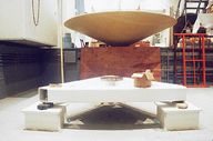
Basic mirror setup
The figure below shows an exploded view of a basic mirror setup. The mirror and bearing are fixed to a three-point mount that aligns the axis of rotation parallel to the gravitational field of the earth. We currently use airbearings because they are convenient for small systems and commercially available units have the required precision and low friction. For larger mirrors it will be preferable to use oil-lubricated bearings as they have greater stiffness and can support substantially higher masses for a given bearing size (we used that kind of bearings for the 3.7 m mirror).
The turntable is driven by a synchronous motor coupled via pulleys and a thin mylar belt made from a length of magnetic tape obtained from a discarded audiocassette. The motor is controlled by a variable-frequency AC power supply stabilized with a crystal oscillator. We control the rotational velocity of the table and thus the focal length of the mirror with the output frequency of the power supply.
A variety of construction techniques have been used to build containers for the liquid, from simple flat plywood disks for 1 meter diameter mirrors to lightweight composite material paraboloids for larger ones. Our latest containers are made of Kevlar laminated over a foam core. The top surface of the containers is created by spincasting a polyurethane resin. To spincast, the turntable is spun while the liquid resin is poured into the container. This resin takes the shape of a parabola and hardens while the turntable is spinning.
To minimize the weight and therefore the cost, and to help dampen effects of disturbances, we have developed techniques that allow us to work with layers of mercury as thin as 0.5 millimeter. A 1 millimeter layer of mercury all over the surface of the 2.5 m mirror requires 5 liters of mercury (about 70 kg). The mercury layer can be thought of as a thin liquid highly reflective coating.
About mercury
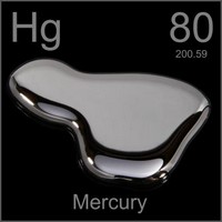
Mercury is a metal that is liquid between -39 and 357 degrees C. It has a density of 13.53 kg/l at 27 degrees C. and a reflectivity of:
- 75.8% at 400nm ( 92.4% for aluminium)
- 77.2% at 600nm ( 91.1% for aluminium)
- 77.6% at 800nm ( 86.7% for aluminium)
- 77.8% at 870nm ( 87.7% for aluminium)
Although mercury is less reflective than aluminium, its surface can easily be cleaned restoring its original shine by skimming dust and other contaminants off the surface layer. This cannot be done as often with conventional glass mirrors. Aluminizing usually takes place once a year, and between these operations, the surface oxidizes, is covered with dirt, and loses its brightness.
Because of the metal's high density, care must be taken in pouring the mercury onto the turntable. Safety posts with wheels were installed to catch the container and protect the air bearing in case of an unbalanced load. Brakes were also installed to stop the mirror in case of power failure before the surface of mercury breaks and causes an instability or to protect the air bearing in case of compressed air leak.
Mercury can be a health risk if it is not manipulated carefully. Masks, gloves, goggles, and proper clothing are used whenever mercury is manipulated. Mercury vapour concentrations in the air are also monitored with a mercury sniffer on a regular basis. We found that a small layer of oxide forms on top of the mercury as time passes. This skin acts as a barrier and inhibits mercury evaporation. Fortunately, this skin is formed evenly and is quite thin (~0.1 micron) so is no impediment to optical quality, but is still extremely effective at cutting evaporation. After about one week spinning, there is practically no mercury vapor around the mirror. This is the reason masks are no longer needed during normal operation of the mirror (as can be seen on the first photograph of this page).
Construction of liquid mirror
Construction of a 3.7 meters liquid mirror
The construction of the 3.7 meters liquid mirror started in April of 1996. Here is, in pictures, a short chronology of the operation.
First, the foam...
The construction of the mirror's container begins with its bottom side. Blocks of styrofoam are glued together with X-40 superglue.
A heated wire is then used to carve the foam into a cone-like shape.
The hot wire has done its job. After removing the excess of foam cut by the wire, we start to work on the central part of the container. The slope of the cone was computed by Robert Content (University of Durham) using finite element software. The foam is sanded to correct irregularities left by the carving. It is now ready to receive the first layer of Kevlar.
Then the Kevlar...
In this photo, we prepare the application of the first layers of kevlar on the central part of the container. We begin with a small layer in the center and each successive layer is slightly larger, ending with a complete surface coverage. This distribution was calculated by Robert Content. The first twenty layers are finished. We use an epoxy glue to laminate the kevlar. The glue takes about 24 hours to dry. After this step, we are done with the central part of the container.
Expanding the structure...
Additional styrofoam blocks are added to the container to increase the mirror's diameter to 3.7 m, its final size. A scaffolding is assembled around the container. Care must be taken to avoid stepping on the high density foam.
The hot wire at work again! The bottom part of the container is carved. Now we will prepare this surface to receive the final layers of Kevlar. On the wall, behind us, you can see the leftover foam carved with the hot wire.
The sanding of the surface is complete and we begin to cover the bottom of the "mirror" with the first full-surface layer of Kevlar.
Additional layers of Kevlar are deposited on the bottom surface. The epoxy glue used to laminate the kevlar will be dry in 24 hours, after which the bottom side of the container will be finished. We are ready to turn it over.
The underside of the mirror is finished. We have to turn the container over to work the top side. This picture, taken half way through the operation, gives a good idea of the mirror's scale.
The three-point mount...
The three points mount is made of 600 kg of steel tubes and plates. It is designed to conteract efficiently any unbalance of the liquid mercury in the container. It was made following a design by Ãric Masson. A liquid mirror has to be precisely levelled. To obtain a good precision, one can either use a large base, or a fine height ajustement on each of the platform's feet. We chose someting in between. We use a commercial
adjustable wedge to level our instrument. The base was complete before the container. You can see us still working in the back of the laboratory. Meenwhile, Gilberto, the photographer, was resting on the side of the pool.
With a touch of paint, our base starts to look like a professional instrument. We install a mechanical bearing and it is ready to receive the container. So far, we have about half of the job done. The container was built near an optical test tower. We only had to move it a few meters to put it on its base. For that purpose, we used a system of chains and pulleys fixed at the center of the container, making the move with relative ease.
Carving the sphere...
For a 3.7 m diameter F/1.2 mirror, the radius of curvature is 8.64 m long. The difference (Peak-to-Valley) between a parabola and a sphere of the same specifications is 0.6 mm. We therefore decided to carve the surface into a spherical shape, technically easier than carving a parabola. For that purpose, we used an 8,74 m steel pipe. The pipe was fixed at the center of curvature of the mirror. To carve the foam, we fixed a milling machine at the end of the pipe. The tool rotates at 20000 rpm and gives excellent results on foam. The container is slowly spun on its bearing while we move the milling machine towards the center. We had to proceed in two steps to make sure we were carving a perfect sphere. We first made an approximate carving and then, once sure the operation was going well, we made the final cut.
The sphere is carved. One can see the foam blocks used to build the heart of the container.
Laminating the surface...
The container is removed from the three point mount. It will not come back until the top side is laminated.
The procedure we used to laminate the top part of the container is quite similar to the one we used for the bottom. We began with 20 smaller layers in the center. It is easier to apply a kevlar layer when the inferior layers are still wet with resin. We therefore applied the final 8 layers in a single day.
Once the kevlar is dry, we put the container back on its three point mount and trim the edge to the correct diameter using the milling machine. To complete the container, we only need to install the rim. We already have a good idea of the final look of the setup.
Installing the rim...
We begin by turning the container upside down. It will be easier for us to work on the rim this way. With this picture, one can easily comprehend the size of our future mirror. A foam ring is installed all around the container. It will be used to hold the edges in place. We than laminate the foam ring with kevlar. It is now part of the setup.
The side of the container is now thick enough to support the rim. The rim , made of thin sheet of kevlar, is glued to the container using a FLOX mixture. We used bolts and washers to hold the sheet in place while the glue set.
And here is the result. Soon, we will spin-cast urethane resin on the container. This will define our parabola.
Spin-casting...
Spin-casting is used to give to the surface of our container a parabolic shape. We used a urethane resin to perform the operation. For optimal results, the resin must be mixed following very precise procedures. The container rotates at the future mirror's optimal velocity so that the resin surface will match the distribution mercury as closely as possible. This will allow us to use only thin layers of mercury. The resin layer is not too thick, so as to minimize the total weight of the container.
The operation is over. It took about 15 minutes. Once the resin has polymerised (and after a few final adjustments) the container will be ready.
Mirror, mirror...
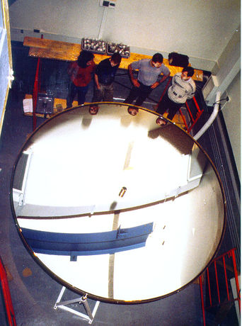
| Here it is at last. A 3.7 meter liquid mirror. The pictures were taken on April 7 1997, 3 days after the mirror was first activated. A thin layer of oxide had formed on the mercury surface 4 to 5 hours after startup, virtually eliminating mercury evaporation. After 3 days there are practically no traces of mercury vapor in the air. The surface of the mirror is 10.75 square meters. The mercury layer is 1.8-mm thick for a total volume of 22 liters of mercury.
| 
|
Optical tests of liquid mirrors
Optical tests of liquid mirrors
Liquid mirrors look nice in photographs, but are they as good as they're supposed to be? This can be verified through standard optical testing. Interferometric tests with Null Lenses give a surface rendering with a precision of ~0.01 micron. Other tests described on this page are useful for quantifying the performances of liquid mirrors.
The testing setup
The surface of the mirror is parabolic and therefore has two conjugate stigmatic points: one at infinity and the other at the focus of the mirror. It is impractical to use a source at 'infinity' for tests in the lab. We therefore settle for the radius of curvature, which is located at twice the focal length of the mirror, along its axis. At this point, the rays from a punctual light source will be reflected back to their origin. If the mirror was spherical, then the image would be almost perfect, with only the slight departures from a perfect sphere contributing to flaws in the image. However, with a paraboloid, spherical aberration appears as one moves from the focus of the paraboloid to the radius of curvature. In effect, each individual circular element of the mirror has its own 'radius of curvature' at which light rays converge back to their source. The position from which we choose to observe the mirror will determine which element is properly imaged.
Spherical aberration can be thought of as an increase of the mirror's slope with increasing radial distance from the center. This aberration is quantified and can be corrected with a set of lenses called null lenses. The image at left shows the setup for testing the mirror. A divergent light source at the radius of curvature illuminates the mirror through a set of two lenses and a folding mirror (all three are part of the null test). The light returns along the same path. The incoming light beam aberrated by the mirror defects, and one simply has to extract the aberration information out of this wavefront. We use different testing instruments, all of them giving an image on a 512 x 480 CCD detector connected to 8-bit framegrabber computer software.
Null lenses
A set of null lenses is usually placed near the center of curvature of the primary mirror under test. It is there to remove unwanted spherical aberration (SA) from the wavefront. The power element (in blue) is designed to add an equal but opposite amount of spherical aberration (It actually creates one half of the mirror's aberration: light passes to and from the mirror, and the linear sum provides a complete correction). This power element is then imaged onto the primary mirror with a field lens (in red) so that both elements that produce SA are very closely spaced.
It can be quite tricky to adjust these lenses to a specific distance from the mirror, on axis with just the right distance between them, and whilst avoiding tilt. The advantage liquid mirrors is that the null lenses must only be adjusted until the onscreen image looks good. This is based on independant tests that showed that the surface of the mirror itself is free of coma and spherical aberration (time-averaged values). We also simulated the setup with an optical ray-tracing software (Code V) to ascertain which aberrations are caused by unavoidable misadjustments of the null test.
Interferometry
One of the instruments we use for radius of curvature testing is an interferometer. An interferometer simply splits a coherent light beam into two parts: a 'measurement' beam and a 'reference beam'. The measurement beam is reflected off the mirror under test and onto a detector, while the reference beam is sent directly to the detector. Following basic wave physics, the measurement beam interferes with the reference and depending on the vertical height of each surface element, interference fringes are produced and can be analysed using computer software. One can then generate a topographical map of the mirror with a precision of a fraction of a wavelength (He-Ne lasers are generally used for this purpose, with λ = 632.8 nm). The above photograph shows a typical interferogram of the 2.5 meter liquid mirror at Laval University. The bright spot in the center of the interferogram is an effect of the scatterplate interferometer, not of the mirror itself. The interferometer is intentionnally tilted so as to produce fringes even on a flat horizontal surface.
The surface map is subsequently compared to a perfect mirror, using a Fourier technique to get the Optical Path Difference. The OPD is twice the surface deviation relative to a perfect mirror.(Twice the distance because the light travels the optical path twice; once from the source to the mirror, once from the mirror to the detector). The OPD map at right represents an average over 8 interferograms, with mean fixed coma, spherical aberration, and focus removed via software before the image was assembled. These subtracted aberrations are caused by misalignments of the null test, and not imperfections on the mirror as discussed above. One can see that the Peak to Valley (Maximum height difference) is of the order of 0.65 wavelengths, or 0.4 microns. The RMS error is 0.079 wavelengths or 0.05 microns. The following image shows the average shape of the liquid mirror.
This image is the result of the analysis of a single interferogram (yes, the one shown earlier on this page). It represents the surface of the mirror at one particular instant in time. As usual, the aberrations from the null test were digitally removed to get only the ones caused by the mirror. P-V distance is 1.4 wavelengths or 0.89 microns, and RMS is 0.138 wavelengths or 0.085 microns. Notice how much of the defects of the image are localized near the edges of the mirror. Images such as this one help us understand the behavior of the liquid mirror under various conditions so that observation can be optimized.
Star tests
Images at left are called Point Spread Functions (PSF). They simply represent what a punctual light source looks like when it has gone through the liquid mirror system. It is also sometimes simply referred to as an artificial star. To perform such a test one shines a bright light through a very small aperture called a pinhole (which can be only a few tens of microns in diameter) at the radius of curvature of the mirror and image it directly onto the detector. Any aberration on the mirror would result in a blurred image of the pinhole. If the mirror is perfect, however, one obtains a well-known pattern called an Airy disk. The image is simply the original pinhole superimposed on a set of concentric rings, caused by diffraction with the edge of the mirror. The two images above are from a star test performed on our liquid mirror, and also happen to closely mimic a perfect Airy pattern.

The photograph at right has a logarithmic intensity scale to enhance the Airy rings. The next image is a PSF calculated from the OPD representing light intensity. Notice the Strehl number, which is a comparison between the height of the measured PSF relative to a perfect Airy pattern. This value of 0.8 indicates us that the mirror is near diffraction limited (i.e. limited only by diffraction at the mirror edges).
Scattered light

Another important part of performance evaluation of large mirrors is a measure of the light scattered far from the central spot (PSF). Imagine a field of stars being observed by a mirror that scatters a large amount of light. Every star in the field would have a large halo around its central peak. The result would be a field of stars with a grayish background and low contrast instead of a dark background and precise, bright white stars. Scattered light measurements are done very much in the same way as the PSF measurments. A point source is imaged by the mirror onto the CCD, and the resulting detected image is normalized with respect to the central spot. We use many images at different exposures, from unsaturated images to highly saturated ones. The image above shows a very saturated image of the point source. The image spans about 80 x 60 arcseconds (one arcsecond is 1/3600th of a degree). The result of such tests is assembled in charts like the one below. Intensity relative to the center of the spot is plotted as a function of distance (center has intensity of 1000).

The graph shows the scattered light during observations using layers of mercury of 3 different depths: 0.5, 0.8 and 1.8 mm. One can see that there are irregular bumps between 13 and 20 arcseconds. These bumps are due to concentric ripples caused by vibrations on the surface of the liquid. The chart shows that these ripples are less prominent on thinner layers of mercury. This is one of the reasons we try to use thinner layers of mercury, and is a good example of how such experimental data is used to fine-tune the instruments under development.
Multimedia
A video showing a liquid mirror in operation is available here:
(right-click to save on hard disk)